You may also like : Know basics of Rocket Science
In this post we will try to familiarize the reader with PSLV rocket and its launch.
PSLV is an acronym for Polar Satellite Launch Vehicle, a rocket that is designed basically for sending satellites into polar orbits i.e. the satellites which move 'vertically' around Earth from Pole to Pole.
PSLV, in its original configuration ( called as ' Core Alone' configuration ) is a 4 stage rocket made up of
- a central core made up of alternating Solid and Liquid motors and
- 4 small Roll Control rockets mounted externally on 1st stage.
This configuration is seen on the right half of of image below.
This configuration is seen on the right half of of image below.
The central Main Core provides the thrust for rising the rocket from ground and then imparting acceleration till the 2nd stage takes over. TheRoll control motors help in navigating the rocket in required trajectory.
 |
PSLV- XL on Left and
PSLV core alone ..... on right
|
This 'Core Alone' model, was used in a few missions which carried lighter spacecrafts, e.g. PSLV C23 ( shown in adjacent image ) which carried SPOT 7 and 4 other small satellites.
When heavier satellites ( or difficult orbit placements ) are to be launched, lift provided by the core alone configuration is not sufficient and so to increase the lift additional rockets are attached. These add-on rockets are called as PSLV Strap On Motors ( PSOM in short ). Like clothes, PSOMs come in two sizes, G and XL.
A smaller version of these motors is PSOM-G, while PSOM-XL is the larger type.
Which type is to be used in a particular mission depends on mission requirement.
In fact even the number of PSOMs attached to the main rocket varies as per depending on mission requirements, 2, 4 or 6 .
PSLV C25, the mission that we are going to cover in detail in a later post, is shown in the photo in the left portion of image. It has 6 PSOM-XL version of strap-on rockets attached to the 1st stage.
In the figure we have intentionally placed both types of rockets side by side for comparison. Notice that the overall height of rocket remains almost same ( Top portion housing payload may vary depending on the cargo size ) for any mission .. only the PSOM portion changes.

PSLV-C25 rocket seen in this image has 6 PSOMs , 3 on Left and 3 on Right. They provide additional thrust to the thrust exerted by the central main rocket.
Notice a small rocket that is visible in front? It is one of the Roll motors. Its complement is on backside and so is not visible.
A question arises, 'Core alone model had 4 PSOMs and here only 2 are seen. Where are the remaining two Roll motors?
 |
| Strap-ons and Roll Motors arrangement around Central core |
Answer is simple. In Core alone mode 4 Roll ons are required to control the movement because they provide a 2 orthogonal axes control. With Strap-on mode, one axis control is by Roll control motors while the other axis control can be achieved by the Strap ons. Hence remaining 2 Roll control motors ( shown by hatched green ) are not necessary.
In the opening sentence we said that PSLV is 'basically' used for launching Polar Satellites. We used the term 'basically' because although the rocket ( From now on we will not use the word rocket .. we will use a more familiar term , VEHICLE, because the rocket, like a car, carries satellites to their desired orbit. ) is originally designed for launching satellites in POLAR orbit, it was used for other purposes also like launching a GTO ( Geosynchronous .. a satellite that moves along equator in a day and so appears to be stationary from Earth ) satellite, Metsat in 2002 ( renamed as Kalpana in 2003, in memory of Kalpama Chawala ). Incidentally the payload satellites are called as Passengers by some users.
Following table gives a compilation of a few configurations used along with the payload weights for comparison. ( GSO = Geosynchronous orbit, SSPO = Sun Synchrnous Polar Orbit and HEO = Highly Eccentric orbit ). Notice that PSLV-C20 mission ( 667 Kgs payload weight ) was launched using Core Alone ( PSLV-CA ) configuration even though the orbit was about 800 Kms compared to about 500 Kms orbit of RISAT-1 ( weighing about 1860 Kgs ). Heavier payloads are launched using -XL configuration.
| Launch Mission | PSLV - C20 | PSLV - C17 | PSLV - C19 | PSLV - C25 |
| Payload | SARAL + 6 | GSAT-12 | RISAT-1 | MOM |
| Weight of Payload (Kgs) | ( 407 + 260 ) 667 | 1410 |
1858 |
1337 |
| Orbit type | SSPO | GSO | SSPO | HEO |
| Orbit size (Kms) | 780 | 284 X 21000 | 480 | 250 X 23500 |
| PSLV configuration | PSLV - CA | PSLV - XL | PSLV - XL | PSLV - XL |
( Note: we are using excerpts from the Doordarshan Transmission of Chandrayan Launch. It will give a guideline about what can be expected and what should be observed in any launch.
You will see following
Service Structure during assembly of Rocket
Rocket standing on its own and the service structure moved away
Umbilicus connecting Rocket with Launch tower
First traces of Ignition ( pilot flame )
All rockets in First stage are ignited
A combined display of Time vs Altitude and Time vs Velocity ( Planned as well as achieved )
Another kind of Display showing Horizontal distance of rocket from Sriharokota.
Still another type of display Tabulating the events and the time of their occurance )
Generally all PSLV launches follow this Sequence..
1. Satellite Design : The satellite is developed at ISAC, Bangalore using components from various ISRO labs or development groups e.g. Student groups ( or abroad in case of a foreign payload ). Depending on the payload the satellite orbit is also finalized.
2. Rocket : The rocket configuration is finalized and the rocket components are produced at VSSC, Trivendrum. A few high precision control components and sensors are produced at less known units of ISRO like IISU, LEOS etc. Rocket motors during design phase are tested at IPRC, Mahendragiri.
 |
| Rocket assembly using Service Structure |
First the central core of 1st stage is put in place followed by the Roll Motors and PSOMs. Then 2nd stage is integrated and so on.
 After the satellite is integrated on 4th stage it is enclosed in a protective enclosure called Heat Shield which protects the satellite from Heat generated by friction with air while rocket is travelling in atmosphere. Heat shield is made up of two halves of conical cylinder which can be split open. ( A heat shield in assembly is seen in this image on left )
 |
| Service structure ( MST ) moved prior to launch |
The rocket is assembled and every stage is checked and rechecked before assembly.
After assembly the MST is moved back by some 150Meters before launch.
Some countries assemble the whole rocket in a different location and then full rocket is transported to launch facility.
4. Countdown : Several hours before the actual launch (generally 3 to 4 days
prior to launch ) the Countdown Starts and every system is checked thoroughly in a very critically planned schedule during this countdown. If any problem is encountered, the countdown goes into 'hold' mode and the after the problem is attended to the countdown resumes.The rocket is loaded with fuel just a few hours before actual launch time and after this nobody is allowed to go near the rocket as per range safety rules. ( But .. at least in one launch we could see a political dignitary first seeing the loaded rocket and immediately going to launch center for witnessing the launch. Power .. more than rocket power :) )
5. Ignition and 1st stage: The Launch activity starts a short time before the actual launch time, T. From this time the sequence is totally automated and no human intervention is generally done unless a crisis situation arises.
Remember, the goal of launch is to place the satellite in desired orbit and so the rocket has to carry the satellite upto required height and impart the required velocity and direction accurately.
 |
First Flame !!!
Roll Control Motors ignited
|
 |
| Umbilicus Cables and Pipes interconnecting Rocket and Launch Tower |
At T=0, the main rocket ( central core of 1st stage ) ignites and in less than 1 sec 4 PSOMs get ignited and the rocket starts rising. These 4 PSOMs are called Ground Lit ( GL ) PSOMs.
In 4/5 seconds from lift off, the vehicle clears the launch pad.
In another 20 to 30 seconds remaining 2 starp-ons ( Called Air Lit ( AL ) strap-ons ) are also ignited.
The flight through the atmosphere is the most difficult maneuver , as it faces numerous aerodynamic forces. About a minute into flight and 4 strap-on motors ( GL Strap-ons ) are separated and fall into ocean. Remaining two AL Strap-ons are separated after another 30 to 40 seconds. The main core however is still burning but the weight reduction of strap-ons which have separated makes the stage more efficient. 1st stage lasts a little over 100 seconds and it separates after that, reducing the rocket weight significantly. Immediately the 2nd stage gets ignited and pushes the remaining lighter load.
As you continue to watch the launch video you will notice that there are 3 types of displays that are continuously shown: One shows the Sequence of events as they happen as after T=0. The time shown is the actual time that they happen. It is because after the GO command given by Mission Director ( a few hours before launch ) , all the events happen under computer control and computer even decides how long the ignition has to happen and when to start and stop. So it reports the actual decisions to experts through this display.
 |
| Display showing events as they happen. |
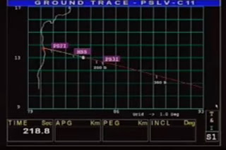 |
| Map showing geographical path of vehicle. |
 |
| A display showing expected and actual progress of Altitude and Velocity. |
Second display shows the velocity of rocket and the altitude that it has achieved with respect to time from Lunch , while a third display shows the motion of rocket on the surface of Earth.
6. 2nd stage and Heat Shield Seperation ( HSS ): The second stage provides the next level of thrust to achieve the required targeted velocity. The 2nd stage burns for about 150 to 160 seconds. While this stage is burning,and since the rocket is much beyond dense atmosphere, the heat shield splits into two parts and gets separated from the body of the rocket, reducing the load that is being lifted. By the time the 2nd stage has finished its job the rocket achieves about 250/260 kms height and velocity of 3-4 kms per second.
7. Third Stage and Coasting: Immediately after the 2nd stage is separated, 3rd stage gets ignited and it burns for about 5 minutes. By the end of Third stage burnout the vehicle achieves about 400 Kms Height with a velocity of about 6 Kms/sec.
After 3rd stage shutdown, the 4th stage is not ignited immediately. So even though there is no active force the vehicle continues to move in the same trajectory for sometime due to the Kinetic Energy that it has attained. This movement with no active force is called as a Coasting and is used cleverly by mission designers to achieve the required orbit placement tasks. We will cover it in detail when we study a launch in detail in a later post.
8. 4th stage and satellite separation: After the coast, 4th stage is ignited and it finally brings the last stage to the desired height and velocity from which the satellite can be released into space. This is a very critical maneuver because the last stage of the rocket should not touch the satellite after its release and so it has to deviate from the satellite's path. The operation becomes more critical when multiple satellites have to be released in a single launch.
9. Mission Control Room : During the launch video you will see several people huddled in a control room. This is Mission control for that particular launch. Actually you will notice that they just clap at specific activity and are not doing anything. True! As the total launch sequence is fully automated and it takes self corrective course to keep the vehicle on its intended path, during actual launch these people just observe. Mind you, they are not just operators, they are various project and operations director but except for one person all of them are just observers and can't do anything from their consoles. And that one person also does not do anything if all is well except for keeping his finger ready to operate the most dreaded switch in that room. That is the D E S T R U C T command switch .. the only command that can be issued by humans during launch sequence which breaks the rocket into pieces. That cool head has to know the minute details of every sequence and also should know when the deviation is beyond control and will cause harm.
Here we talked about the rocket launch alone. Actually there are other agencies also who monitor the flight continuously. There is an international network of satellite tracking antennas which become active in almost any launch that takes place anywhere in the world. It is required because the rocket can be tracked from launching station only for a few hundred kms and beyond that it goes below horizon so another station has to takeover and relay telemetry data to mission control room.
Back to Main Index
Good description and explaination. But why use chandrayaan video when other PSLV launch videos are also seen on youtube?
ReplyDeleteTrue Anonym.. Thanks for observation. But I could not find a complete video of any other PSLV launch. Even this is not complete but at least it could give me all the various points that I had intended to cover. Will try recording a full launch if technically feasible with my home grown equipments during next launch(es).
ReplyDeleteVery nice!
ReplyDeleteverrry interesting
ReplyDeleteThanks Planet Stories and Anonymous for the interest.
ReplyDeleteGives a boost to write more.